- 您现在的位置:买卖IC网 > Sheet目录381 > 426013700-3 (Digital View Inc)CABLE EXT PWR IN 4WIRE LEADS
�� �
�
�APPLICATION� NOTES�
�USING� THE� CONTROLLER� WITHOUT� BUTTONS� ATTACHED�
�This� is� very� straightforward:�
�?�
�?�
�?�
�?�
�Firstly� setup� the� controller/display� system� with� the� buttons.� With� controls� attached� and� display� system� active� make� any�
�settings� for� colour,� tint� and� image� position� as� required� then� switch� everything� off.�
�Remove� the� control� switches,� the� 12-way� (CNC1)� cable.�
�Use� a� jumper� or� similar� to� connect� pins� 1� &� 2� on� CNC1,� this� will� fix� the� board� On.�
�Refer� to� inverter� specifications� for� details� as� to� fixing� brightness� to� a� desired� level,� this� may� require� a� resistor,� an� open�
�circuit� or� closed� circuit� depending� on� inverter.�
�Summary� :� On� CNC1� the� only� pins� that� are� used� are� for� On/Off� and� Brightness� (if� controller� mounted� inverter� is� used).� On�
�CNC1� the� pins� are� for� momentary� type� buttons� so� it� doesn’t� matter� that� no� buttons� are� attached.�
�INVERTER� CONNECTION�
�There� are� potentially� 3� issues� to� consider� with� inverter� connection:�
�?�
�?�
�?�
�Power�
�Enable�
�Brightness�
�Please� read� the� following� sections� for� a� guide� to� these� issues.�
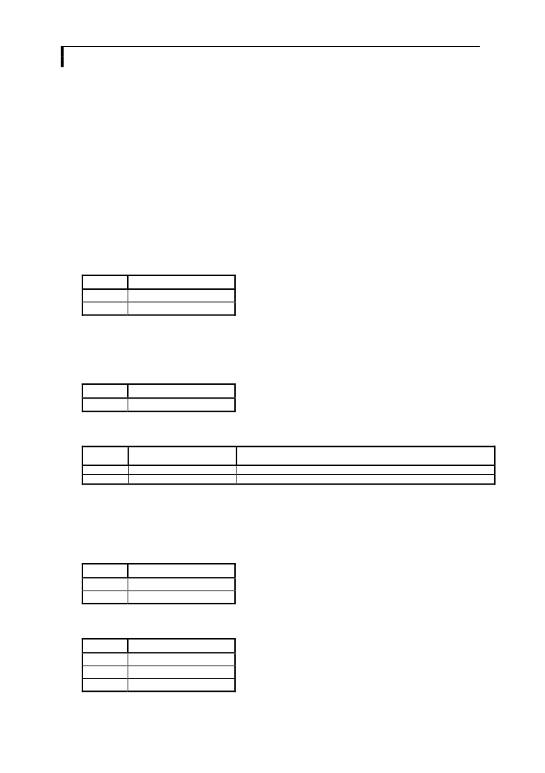
�Inverter� Power� :� As� per� the� table� for� CNB1� pin� 1� is� ground� and� pin� 2� provides� 12V� DC.� This� should� be� matched� with� the� inverter�
�specification:� see� table.�
�CNB1�
�PIN�
�1�
�2�
�DESCRIPTION�
�Ground�
�+12VDC�
�Remark:� For� higher� power� inverter,� more� current� (for� 12V)� can� be� taken� from� CNA1� pin� 1.�
�Enable� :� This� is� a� pin� provided� on� some� inverters� for� On/Off� function� and� is� used� by� this� panel� controller� for� VESA� DPMS�
�compliance.� If� the� inverter� does� not� have� an� enable� pin� or� the� enable� pin� is� not� used� then� DPMS� will� not� be� operational.� Pin� 3�
�should� be� matched� to� the� inverters� specification� for� the� ‘enable’� or� ‘disable’� pin.�
�CNB1�
�PIN�
�3�
�DESCRIPTION�
�Enable�
�Further,� jumpers� JB2� &� JB3� should� be� set� to� match� the� inverters� specification� for� the� enable� pin� power� and� High� or� Low� setting:�
�see� table.�
�Ref�
�JB2�
�JB3�
�Purpose�
�Inverter� enable� voltage�
�Inverter� control�
�Note�
�1-2� H� =� 12V,� 2-3� H� =� 5V� (Vcc),� OPEN� H� =� open� collector�
�1-2� H� =� On,� 2-3� L� =� On�
�Brightness� :� There� are� various� methods� for� brightness� control� and� it� is� important� to� consider� the� specifications� for� the� inverter� to�
�be� used.� Generally� the� situation� is:�
�?�
�?�
�?�
�Brightness� can� controlled� by� using� a� resistor� or� VR� (Variable� Resistor).�
�Brightness� controlled� by� adding� a� circuit� such� as� PWM� (Pulse� Width� Modulation).�
�No� adjustment� of� brightness� is� possible.�
�CNB1� pins� 4� &� 5� are� available� for� connecting� to� an� inverter� or� circuit� where� VR� control� is� supported.�
�CNB1�
�PIN�
�4�
�5�
�DESCRIPTION�
�VR� WIP�
�VR� A�
�This� can� then� be� matched� with� function� controls� connected� to� CNC1� pins� 4� &� 3� or� 5:� see� table.�
�CNC1�
�PIN�
�3�
�4�
�5�
�DESCRIPTION�
�VR� A�
�VR� WIP�
�VR� B�
�24�
�发布紧急采购,3分钟左右您将得到回复。
相关PDF资料
426090200-3
CABLE SERIAL IN RS-232 CONN
426120410-3
CABLE OSD 12-WAY 610MM
4268-00
KIT EVAL FOR 4268 RF SWITCH
4270-00
KIT EVAL FOR 4270 RF SWITCH
4271-00
KIT EVAL FOR 4271 RF SWITCH
4272-00
KIT EVAL FOR 4272 RF SWITCH
4273-00
KIT EVAL FOR 4273 RF SWITCH
42742-03
KIT EVAL FOR 42742 RF SWITCH
相关代理商/技术参数
426013800-3
功能描述:电缆组件 PP5/12V Pwr Input 160mm 2.5mm conn
RoHS:否 制造商:Molex 产品:Power Assemblies 类型:Cable Assembly 连接器端口 A:No Connector 连接器端口 A 管脚计数:4 连接器端口 B:No Connector 连接器端口 B 管脚计数: 型式:Male 线规 - 美国线规(AWG):20, 28 长度:0.305 m 颜色:Black, Red
426015100-3
功能描述:电缆组件 Cable Power-In 380mm
RoHS:否 制造商:Molex 产品:Power Assemblies 类型:Cable Assembly 连接器端口 A:No Connector 连接器端口 A 管脚计数:4 连接器端口 B:No Connector 连接器端口 B 管脚计数: 型式:Male 线规 - 美国线规(AWG):20, 28 长度:0.305 m 颜色:Black, Red
426016100-3
功能描述:电缆组件 CHANNEL SEL CBL FOR DVC-RX. 100MM
RoHS:否 制造商:Molex 产品:Power Assemblies 类型:Cable Assembly 连接器端口 A:No Connector 连接器端口 A 管脚计数:4 连接器端口 B:No Connector 连接器端口 B 管脚计数: 型式:Male 线规 - 美国线规(AWG):20, 28 长度:0.305 m 颜色:Black, Red
4260164702
制造商:DDP 功能描述:
4260-1647-22
制造商:Bourns Inc 功能描述:
426016900-3
功能描述:CABLE POWER IN 400MM 制造商:digital view inc. 系列:* 零件状态:在售 标准包装:1
42-602
制造商:Ideal Industries Inc 功能描述: